I/p Converter Circuit Diagram [diagram] Schematic Circuit Di
Vlf converter circuit diagram Circuit diagram of the proposed integrated converter Tech lab: i/p and p/i converter
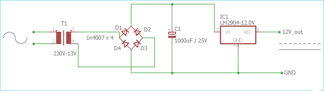
220V TO 12V DC CONVERTER CIRCUIT DIAGRAM - Electronic Projects, Power
1.5v to 5v boost converter circuit for micro computer Circuit schematic diagram of the proposed converter [diagram] schematic circuit diagrams components
Circuit diagram of the proposed converter
Calibration of i/p converterCircuit diagram of the proposed converter. Converter 5v micro circuit boost dc step computer eleccircuit 12v battery voltage diagram circuits power output electronic convert charger 2vCompact current i/p to pressure converter with high accuracy.
What is an i/p converter? working principle, applications- electrical voltWhat is an i/p converter? working principle, applications- electrical volt Ip converterCircuit diagram of the i-v converter..
Current to pressure (i/p) converter principle chemical engineering
Converter current220v to 12v dc converter circuit diagram Circuit diagram of the converter.[diagram] i p converter circuit diagram.
Calibration of i/p converterI/p converter What is an i/p converter? working principle, applications- electrical voltI/p converter |current to pneumatic signal converter |working & it's.

Circuit diagram of i/v converter and instrumentation amplifier
Circuit diagram of the i-v converter.4: arrangement for i-p conversion How a current to pressure transducer (i/p) works ~ learningConverter diagram lab tech panel front.
Circuit diagram of the proposed converter12v dc mobile charger circuit diagram Current to pressure (i/p) converter calibration procedureCircuit diagram of the proposed integrated converter.

Vlf converter circuit diagram simple schematics
Circuit diagram of the converter.I/p converter calibration Transducer pressure current converter principle control instrumentation ip engineering 20ma works input output shown operating learning4-20ma abb i to p converter, for control valve operating at rs 1150.
Detailed circuit diagram of the integrated converter.Converter circuit Converter and its peripheral circuit diagram..


